



What is the working process of a ball mill?
Ball mill motors are very important pieces of equipment in places around the world that process minerals, make cement, and make chemicals. When choosing the right drive systems and making the most of production output, it's important to understand how they work. A special motor inside a ball mill drives a continuous grinding process that turns raw materials into fine powder. The circular drum spins horizontally and holds grinding media, which are usually steel balls or ceramic spheres. The media fall and roll, repeatedly hitting and wearing down the materials they are breaking. To get the particles to the right size, this mechanical reduction process needs precise motor control, management of spinning speed, and steady power delivery.
Understanding the Working Process of a Ball Mill
Material Feeding and Initial Distribution
The circular trunnion at one end of the cylinder shell is how operators put raw materials into the mill. The feed size is usually between 20mm and 25mm, but it can be any size based on the job. The material and grinding media are spread out evenly inside the chamber by centrifugal forces as the drum turns. This first part of distribution is very important because uneven loading causes uneven forces that put stress on the drive motor and make grinding less effective. Modern feeding systems have variable speed settings that make sure that the material is fed in sync with the drum's spinning. This stops sudden spikes that could damage the motor or leave empty spaces inside the mill.
Rotational Grinding Through Impact and Attrition
Once the material is spread out evenly, the main grinding action of the mill starts. The motor of the ball mill spins the drum at a set speed, usually between 65% and 75% of the critical speed. The grinding media rises along the inside wall of the drum and then falls back down. This sliding motion creates two different ways of grinding: impact crushing happens when balls fall from a height and hit bits of material, and attrition grinding happens when balls next to each other tear and rub against each other. The motor has to keep its spinning speed steady even when the load changes, because changes in speed have a direct effect on how the particles are distributed and how much energy is used. Mills that are running too slowly lose energy by sliding around too much, and mills that are running too fast cause centrifugal forces that stop grinding from working properly.
Product Discharge and Classification
When the particle size meets the requirements, the ground material comes out of the mill. When the slurry level reaches the discharge trunnion of an overflow discharge system, the material can naturally flow out. Grate discharge mills, on the other hand, have internal grates that only let very small particles pass through. To keep the mill loaded properly, the discharge rate and feed rate must be equal. This is done with complex motor control systems that change the speed of rotation based on the mill's weight, power use, and sound signatures. In more advanced systems, variable frequency drives are built into the ball mill motor. This lets operators adjust the rate of discharge without stopping work.
Key Ball Mill Motor Types and Specifications for Industry Applications
To choose the right motor technology, you need to know how the different types of motors handle the specific needs of grinding processes. Ball mills have high starting loads, heavy-duty cycles that go on all the time, and sometimes shock loads from big feed particles.
AC Induction Motors for Standard Applications
Standard ball mill setups use three-phase squirrel cage induction motors because they are strong, don't need much upkeep, and have been shown to work well in dusty places. There is no physical link between the rotor and the stator in these motors; instead, electromagnetic induction turns electrical energy into mechanical rotation. Rated voltage ranges from 3kV to 11kV, so they can work with a wide range of plant electrical systems and keep current losses to a minimum in long cable runs. Power levels between 400kW and 15,000kW cover mills of all kinds, from small ones used in laboratories to huge ones that process hundreds of tonnes of material every hour. The wound rotor version has a drilled shaft design that lets external resistance be added during starting. This lowers the inrush current but lowers the starting power. Non-drilled shaft motors are better at starting because they can reach torque ratios of 1.7 at rated voltage. This makes them better for installations that don't have soft-start equipment.
Synchronous Motors for Large-Scale Operations
When mill power goes over 5,000kW, large grinding systems are choosing synchronous motors more and more. Unlike induction motors, synchronous motors keep the same speed no matter how much load is on them. This makes the grinding conditions very stable, which improves the quality of the output. These motors can also fix the power factor, which lowers reactive power charges and raises the electricity efficiency of the plant. The technology needs more complex control systems, such as activation tools and synchronisation screens, but it works 2-3% more efficiently than similar induction motors. This efficiency advantage saves a lot of energy over many years of use, which usually pays for the higher initial investment within 18 to 24 months.
Variable Frequency Drive Integration
In modern installations, motors are paired with variable frequency drives that change power from the grid, which has a fixed frequency, into output with an adjustable frequency. By integrating a VFD, soft starting is possible, which slowly speeds up the mill from a stop to full speed over 30 to 60 seconds. This avoids the mechanical stress and electricity spikes that come with direct-online starting. During normal operation, drives change the motor speed to keep the best conditions for grinding, even though the feed features change from shift to shift. The frequency conversion feature works with both 50Hz and 60Hz, which makes it easier to standardise equipment for operations that take place across borders. Protection levels from IP00 to IP55 can be used in a wide range of settings, from clean control rooms to dusty mill floors.
Motor Design Features for Continuous Operation
Ball mill motors are made with special parts that make sure they work reliably 24 hours a day, seven days a week, even in difficult circumstances. Class F or H insulation systems can handle the high winding temperatures that come from running at full load for a long time. IC01, IC37, and IC81W cooling methods can handle temperatures ranging from very cold to very hot. Frame sizes from 1730mm to 4250mm are available so that they can fit in a variety of mill setups. With 20, 24, 30, 32, 36, 40, 48, and 60 poles, the motor output can be precisely matched to the mill's needs without the need for an intermediate gear. Low-speed operation between 100 and 300 rpm keeps mechanical wear to a minimum while still providing the high torque needed to turn drums that are heavily loaded. The IM7311 mounting setup works with both pinion-driven and direct-drive installs, which gives you options when planning the layout of your plant.
Enhancing Ball Mill Motor Efficiency and Performance
In grinding processes that use a lot of energy, operational efficiency has a direct effect on production costs. Electricity costs usually make up 30 to 50 percent of all milling costs, so improving motor performance is a top priority for procurement professionals and plant engineers.
Identifying Performance Bottlenecks
There are energy losses all along the chain from the ball mill motor to the mill. 2-4% of the power that goes into the motor is wasted as heat due to resistive losses in the windings. Another 1-2% is lost due to mechanical friction in the bearings and cooling fans. When the motor and gearbox are not lined up correctly, vibrations happen, which wastes energy and speeds up the wear on parts. Motors work outside of their most efficient range when they are running at speeds that aren't ideal. This is especially true in fixed-speed setups that can't adjust to changing mill loads. Periodic overloading, which can be caused by feed particles that are too big or too much mill filling, causes current surges that put stress on insulation systems and shorten the life of motors.
Energy-Saving Technologies and Best Practices
IE4 energy class ratings are reached by high-efficiency motor designs with better magnetic circuit designs, premium-grade electrical steel laminations, and better cooling systems. When compared to their standard-efficiency peers, these motors use 15-20% less energy, and in continuous-duty uses, they pay for themselves in less than two years. By using VFD control, motors can work at their most efficient level even when the load changes, instead of always going at full capacity. When you choose the right motor size, you can avoid chronic underloading, which lowers the power factor and efficiency. During normal production, motors should run between 65 and 95% of their rated capacity. Regular upkeep, such as greasing the bearings, cleaning the cooling system, and fixing the connections, keeps the efficiency from dropping over time.
Condition Monitoring and Predictive Maintenance
Monitoring tools that are more advanced keep an eye on motor factors that show problems before they happen. Vibration sensors find worn bearings, misaligned rotors, and imbalanced rotors. Thermal imaging finds hot spots that mean insulation is breaking down or cooling system blockages. Power quality analysers show when there are problems with the supply voltage and harmonic distortion, which puts stress on motor parts. A lot of operators now use constant tracking systems that send data to cloud platforms so that it can be analysed. This lets maintenance teams plan their work for planned shutdowns instead of having to deal with problems that happen out of the blue. This method of planning ahead cuts unplanned downtime by 40–60% and increases the life of motors.
Emerging Motor Technologies
Permanent Magnet Motors are the next version of mill drive technology. They are 4-6% more efficient than traditional designs because they don't lose any power in the rotor. These motors keep their full torque even when they're not moving, which makes starting easier and opens up new ways to run things. Motor controllers have built-in smart monitoring systems that constantly check themselves and find changes in bearing state, insulation resistance, and winding temperature that aren't normal. Improvements in material science make insulation systems that can survive temperatures 20 to 30°C higher than current standards. This lets designs be smaller while still having the same thermal reserves.
Comparing Ball Mill Motors: Selecting the Best Motor for Your Grinding Application
When making choices about what to buy, you have to weigh professional ability against capital costs, running costs, and the supplier's skills. Figuring out the differences between the different types of motors keeps you from making costly mistakes.
High-Torque Motors for Heavy-Duty Applications
Mining and primary cement grinding require motors that can start mills that are fully loaded and handle shock loads from oversized feed on occasion. Non-drilled shaft motors have starting torque ratios of 1.7 and pull-out torque ratios of 2.0. This gives them the mechanical reserve they need for these tough jobs. Even though the starting current ratios are 7.0, the strong build can handle the heat and mechanical pressures that come with starting it up many times. Largest production mills can be powered by up to 15,000kW, and low-speed designs (100–200 rpm) mean that many direct-drive systems don't need speed-reduction gears.
Standard Motors for Moderate Grinding Duties
When secondary grinding and finish milling are done, the loads are usually smaller and more stable, which lets you choose more cost-effective ball mill motor types. Drilled shaft motors use less power to start up, but their lower starting force (ratio of 0.6) means that soft-start equipment or a mill that isn't loaded with anything during startup is needed. These motors are 15–25% cheaper than similar ones that aren't drilled, but they work just as well in steady state. Most industrial grinding installations fall in the moderate power range (400–5,000kW), and standard efficiency designs work well when the cost of electricity is low.
Motor Versus Gearbox-Driven Configurations
In direct-drive mills, the motor shaft is directly connected to the mill trunnion through an air clutch or a flexible coupling. This setup cuts down on mechanical losses by 2% to 3% and gets rid of the need for gearbox maintenance, but it needs expensive, large-diameter motors that run at low speeds. When you combine smaller, faster motors with reduction gearing, you get gearbox-driven systems. These have lower start-up costs and more installation options. But the total running costs go up because the gearbox loses efficiency (usually 2% to 4%), and it needs to be maintained (oil changes, gear tooth inspections, etc.).
Evaluating Motor Specifications for Application Matching
To choose the right motor, you must first figure out how much power the mill actually needs based on your output goals, the hardness of the rock, and the amount of the grind you want. As a general rule, 15-20 kWh per tonne of material processed, but the real numbers depend a lot on the properties of the material. Safety factors between 1.15 and 1.25 take into account changes in the process and future growth in capacity without making motors too big. The speed setting must put the mill running at 70–75% of its critical speed. This means that the motor rpm, drive ratio (if used), and mill width must all work together. To avoid adding more transformers, the voltage should match the plant's existing electrical infrastructure. The starting method (direct-online, soft-start, or VFD) should be chosen based on the plant's mechanical constraints and the grid's capacity.
Ball Mill Motor Procurement Guide for B2B Buyers
A successful procurement process includes more than just technical specifications. It also includes evaluating suppliers, negotiating prices, and setting up long-term support plans. Making strategic decisions about where to get things affects not only the costs up front, but also the reliability of operations over many years.
Identifying Reliable Motor Suppliers
Facility certifications (ISO 9001 quality management and ISO 14001 environmental management), product certifications (CE for European markets, UL for North America, and CCC for China), and technical accreditations are all ways that qualified providers show they can make things. Online study in industry listings and business-to-business (B2B) platforms gives you the first list of suppliers, while going to mining equipment shows lets you talk to people in person about technical issues and build relationships. By asking for customer reference lists and visiting setups that are already up and running, you can find out how well the product works and how good the supplier's help is. When it comes to service response times and the availability of extra parts, local distributors are better, but direct maker ties offer better prices and more customisation choices for big projects.
Pricing Structures and Commercial Terms
Prices for motors change a lot depending on the specs, the number of orders, and the state of the market. Margin prices for standard motors under 1,000kW are usually between 15 and 25 percent, while margin prices for custom-engineered big motors are between 30 and 40 percent. Orders of more than one unit qualify for volume discounts of 5 to 15%, and framework agreements for ongoing supply save you even more money by lowering the costs of doing business. The standard guarantee covers the product for 18 months after it is put to use or 24 months after it was shipped, whichever comes first. Extended warranty programs cost between 3 and 8 percent of the motor's value a year, but they're worth it for important uses where unplanned downtime can cost a lot. Payment terms usually require a 30% deposit when the order is placed and the rest before shipment. However, repeat buyers may be able to arrange net-30 or net-60 terms.
Customization Capabilities and Lead Times
Standard motor specs work for 70–80% of ball mill uses, but sometimes they need to be changed to fit special needs. Common changes that add 2 to 4 weeks to standard delivery times are voltage adjustments, special shaft configurations, different mounting arrangements, and higher protection grades. It takes 16 to 24 weeks from the time an order is confirmed until the motor is shipped if it has unusual power ratings, special materials for corrosive environments, or built-in monitoring systems. ODM suppliers can make completely new motor designs that are perfect for certain uses, while OEM agreements let buyers get motors that are labelled with their own company name.
After-Sales Support Infrastructure
The quality of technical support is what sets true partners apart from commodity suppliers. Full support includes overseeing the installation, helping with the starting process, teaching operators, and setting up regular upkeep plans. Response times are faster when suppliers have local service centers. For example, site visits usually take 24 to 48 hours, while overseas deployment takes 5 to 10 days. Downtime for maintenance is directly affected by the supply of spare parts. Crucial wear items like bearings, heat sensors, and terminal blocks should be kept in stock locally, while less common parts may be sent from regional stores. Service agreements that spell out response times, part prices, and emergency support procedures give you peace of mind while the motor is in use.
Conclusion
Learning the basics of how a ball mill motor works gives buying workers the power to choose motors that combine technical performance, operating efficiency, and business value. Grinding efficiency and production costs are directly related to the starting power, speed stability, and heating capacity of the motor as well as the mill's gears. Long-term results are better when you compare motor types, evaluate supplier expertise, and base your buying decisions on the total cost of ownership instead of the original price. Grinding operations are under increasing pressure to reduce energy consumption and improve reliability. To stay ahead in global markets, they need to work with suppliers that provide advanced motor technologies, comprehensive technical support, and practical application expertise.
FAQ
1. What determines the optimal motor size for a ball mill?
Motor sizing depends on mill dimensions, material characteristics, and throughput requirements. Calculate based on 15-20 kWh per ton processed, then apply safety factors of 1.15-1.25. Verify that motor torque exceeds mill starting requirements at the specified operating speed.
2. How do drilled shaft and non-drilled shaft motors differ?
Non-drilled shaft motors deliver higher starting torque (ratio 1.7 versus 0.6) and better starting capability, making them suitable for heavy-duty applications. Drilled shaft designs require air clutches and draw lower starting current, fitting installations with electrical limitations or soft-start systems.
3. What maintenance extends motor service life?
Regular bearing lubrication, cooling system cleaning, and electrical connection inspection prevent premature failures. Vibration monitoring detects developing mechanical problems, while thermal imaging reveals insulation stress. Properly maintained motors routinely exceed 20-30 years of operational life.
Partner with SYSX MOTOR for Reliable Ball Mill Motor Solutions
SYSX MOTOR specializes in manufacturing high-performance motors engineered specifically for demanding grinding applications. Our comprehensive product range spans power ratings from 400kW to 15,000kW, incorporating advanced design features that deliver exceptional starting torque, sustained speed stability, and industry-leading efficiency. As an established ball mill motor manufacturer with certifications including CE, UL, IEC, and GB compliance, we support mining, cement, and chemical processing operations across six continents. Our engineering team provides customized motor solutions tailored to your operational requirements, while our global service network ensures responsive technical support and rapid spare parts delivery. Contact our technical specialists at sxmotor@yeah.net to discuss your specific grinding application requirements and discover how our motor technology can optimize your production efficiency.
References
1. Wills, B.A. and Finch, J.A. (2015). Wills' Mineral Processing Technology: An Introduction to the Practical Aspects of Ore Treatment and Mineral Recovery. 8th Edition, Butterworth-Heinemann, Oxford.
2. Tuzcu, E.T. and Rajamani, R.K. (2011). "Modeling Breakage Rates in Mills with Impact Energy Spectra and Ultra Fast Load Cell Data," Minerals Engineering, Vol. 24, No. 3-4, pp. 252-260.
3. Napier-Munn, T.J., Morrell, S., Morrison, R.D., and Kojovic, T. (1996). Mineral Comminution Circuits: Their Operation and Optimisation. JKMRC Monograph Series in Mining and Mineral Processing, University of Queensland, Brisbane.
4. International Electrotechnical Commission (2014). IEC 60034-1: Rotating Electrical Machines – Part 1: Rating and Performance. IEC Standards, Geneva.
5. Reichert, M., Gerold, C., and Kocsis, K. (2015). "Investigation of Mill Speed and Mill Power in a Grinding Circuit," Minerals Engineering, Vol. 86, pp. 24-34.
6. Kawatra, S.K. (2006). Advances in Comminution. Society for Mining, Metallurgy, and Exploration, Littleton, Colorado.

USER EVALUATE
Here is the customer's evaluation of us
YOU MAY LIKE
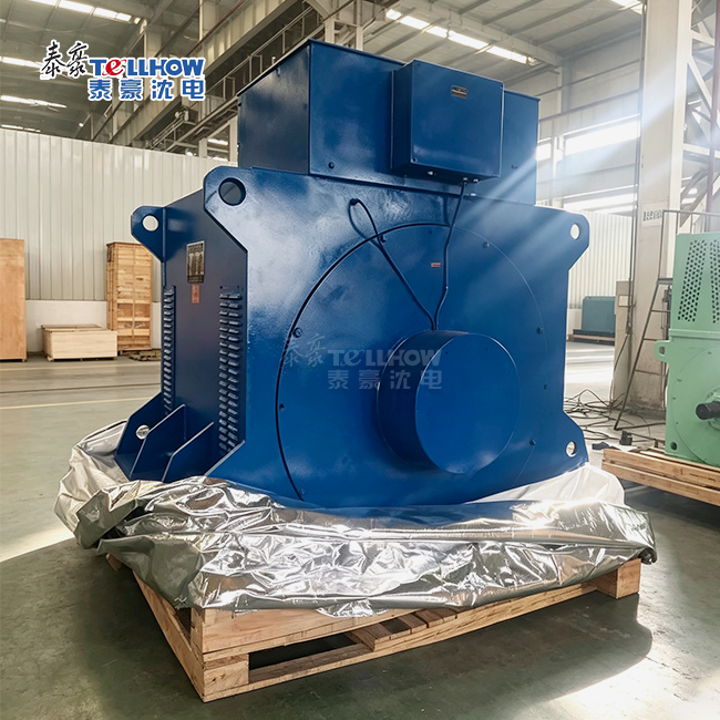 VIEW MOREhydro water turbine generator
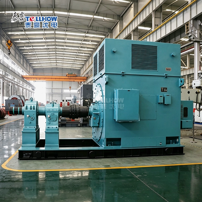 VIEW MOREopen type high voltage slip ring motor
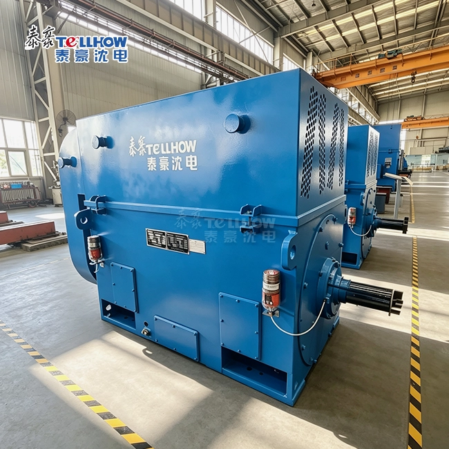 VIEW MOREThree Phase AC Motor For Draught Fan
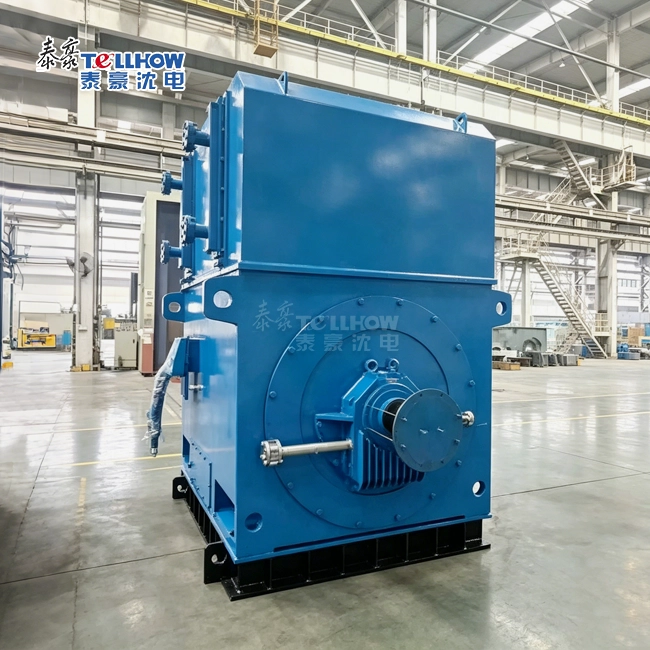 VIEW MOREHigh Torque Coal Mill Motor
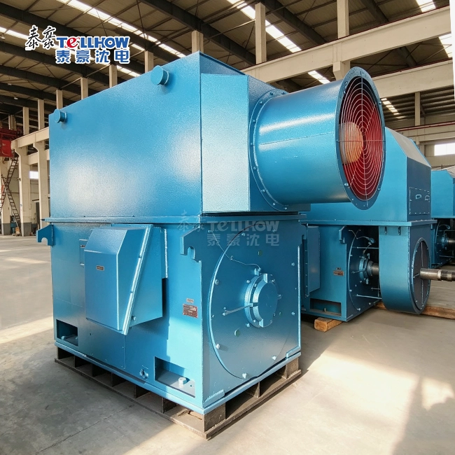 VIEW MOREVariable frequency squirrel cage motor
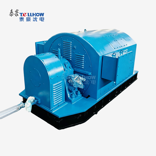 VIEW MORE3600rpm circulating Pump Power Plant Motor
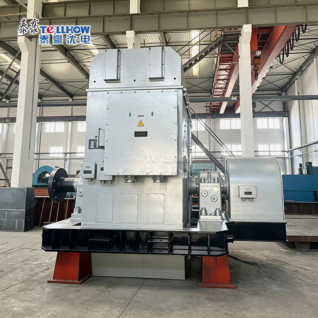 VIEW MOREPositive pressure increased safety synchronous motor
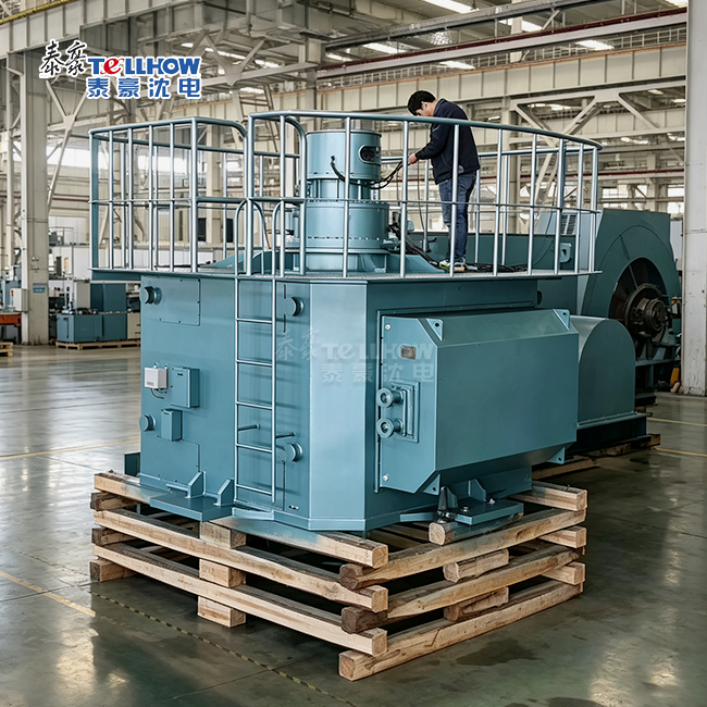 VIEW MORESynchronous motor for circulating water pump